
|
|
|
The setup is based on the research, design, and main parts from Web3.0 and others from Spyderchat.com. The basic layout and function is the same but many things have been added, changed, or tweaked. The core of the system is a Rotrex C30-94 centrifugal style supercharger that is easily capable of 400 hp with adiabatic efficiency around 76-80%. Normal superchargers like Roots style run 40-50% and are prone to heat soak. Rotrex is best known for their use in the Koenigsegg CCX and CCXR producing over 1000 bhp. This setup uses an air to water to air intercooler. Cold ambient air coming in the front grill passes through the air to water heat exchanger which cools the water/ethylene glycol (radiator fluid). That cooler water is pumped using an electric water pump from a Ford Lightning to the rear of the car where it passes through the water to air heat exchanger. This cools the intake air charge which gets heated from the compression by the supercharger. The intake air charge, now cooled, passes through the Mass Airflow Sensor which measures flow and temperature to allow the ECM to match the appropriate amount of fuel. This system provides cooler air and much less heat soak to create more power all the time. The thermodynamic interaction and the nature of the belt driven supercharger produces a steadily increasing amount of power as the engine RPM increases. There is no turbo lag effect and the delivery is smooth and predictable all the way up the range and then you need to shift. When you let off the gas and the throttle quickly closes, the re-circulating blow off valve redirects the boosted air back into the intake tract before the supercharger thus allowing the charge to prevent surge and vent to atmosphere or get sucked back into the intake flow. This also greatly reduces the annoying blow off valve sound that some may actually enjoy. I adjusted the spring rate of the BOV to match the system characteristics and it works great. The rest of the setup involves the re-routing of the PCV, CCV, EVAP systems. To achieve the best crankcase ventilation, I have routed the lines to the suction side of the supercharger to pull the gases from the valve cover. This oil infused air passes through a dual catch can filter setup to remove the oil so it doesn't deposit on the supercharger vanes or intake manifold. The catch cans use special thin wall technology by Saiko Michi. and really are a work of art. Also, KrankVents are used to prevent boosted air from pressurizing the crankcase during normal driving where the intake pressure is less than atmosphere. The result of all this is a daily drivable fun car that can throw you back into your seat when you get on it. For the real gear heads, this setup allows you to achieve massive amounts of power by strengthening the internal parts of the engine like rods, pistons, bearings, etc, and only changing a pulley on the supercharger. The MAF is undersized and capable of more power than you will ever need from a 1ZZ or 2ZZ so it is just a matter of upgrading your engine. If you want more power with an inexpensive modification, simply replace the factory downpipe, cat, and exhaust with a high flow or eliminated cat and a high flow exhaust. PPE, Che, Team Moon, and some others make great options. I estimate you will get the extra 20 hp that I couldn't during tuning because of the flow restrictions. |
|
Here is a diagram of the general setup for your reference. |
|
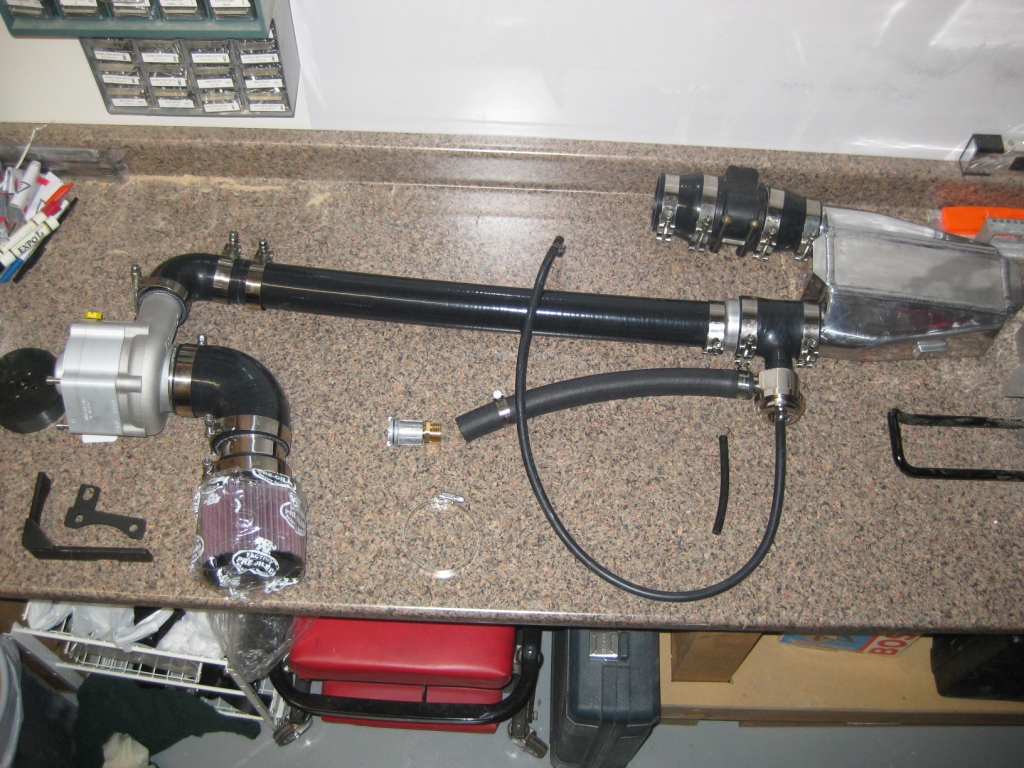
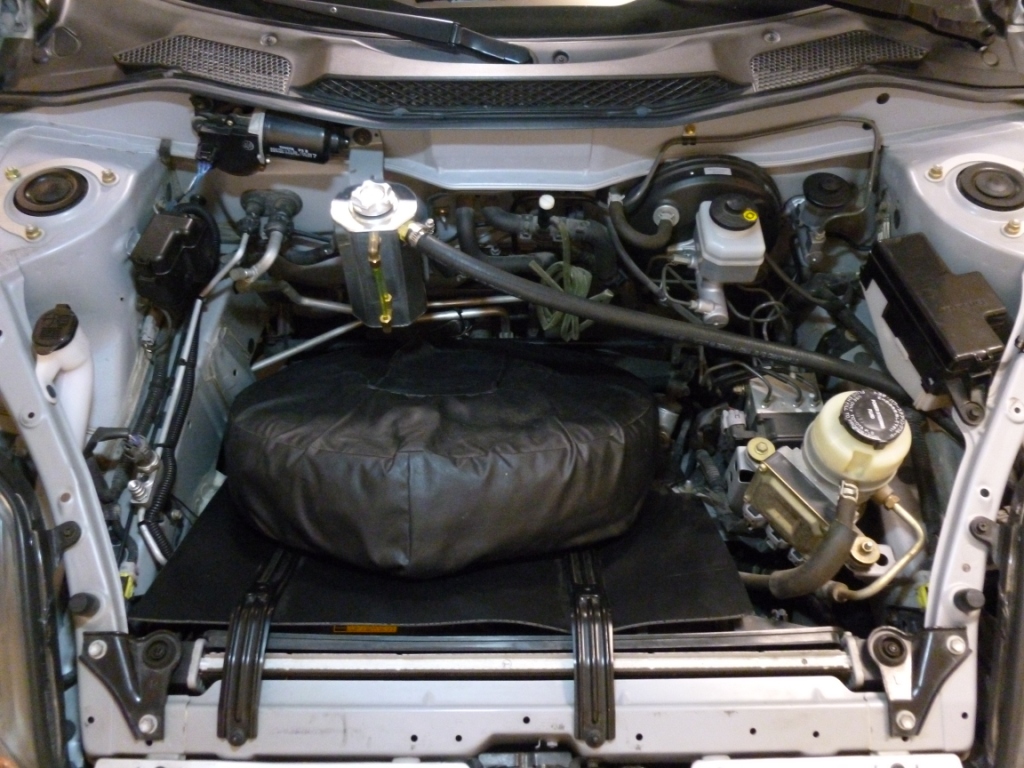
Here is the initial setup before I installed it. This is the best view of the main parts. Since all of this portion is sandwiched between the engine and the firewall, it is difficult to see it now from the engine bay. |
|
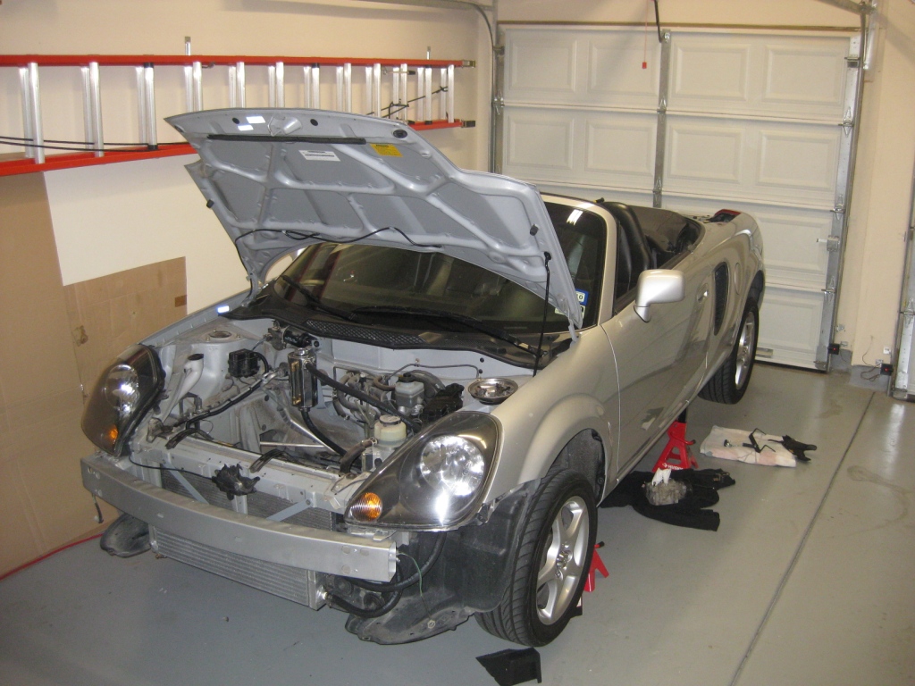
This picture shows the installation of the front mounted air to water intercooler. It is well supported on the top and bottom to the front chassis members. |
|
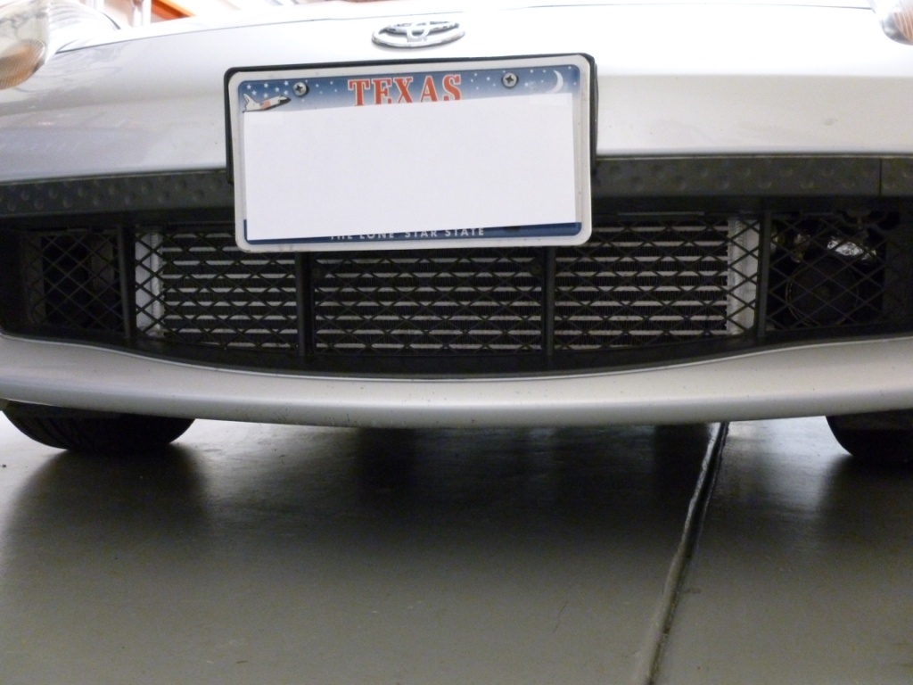
The intercooler looks pretty cool in my opinion to those who look for such things but doesn't really stand out to the untrained eye. It is pretty subtle yet looks intimidating through the plastic grill mesh. |
|
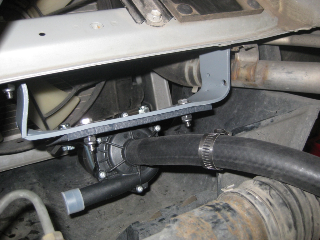
Securely mounting the electric water pump to the front frame rail. The custom bracket includes Poron foam to insulate the pump and reduce audible vibration. The water system is easy to drain with drain cocks at the low points of the hoses and is easy to fill using an auxiliary 12V power supply. The pump quickly takes away cavitation and is running perfectly in just a few minutes. The reservoir easily tells you the level of the fluid, though this doesn't really change because there are no leaks. Also, the fluid doesn't really deteriorate because it doesn't experience the high temperatures of the engine block. There is a Type K sealed thermocouple installed just after the pump to measure the A/W/A coolant temperature before getting passed through the I/C. |
|
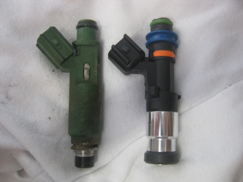
This picture shows the stock fuel injector (left) and the 700cc injector from MWR. These injectors can do 325hp with the stock rail and 450hp with a regulator pump, and returning rail. These need to be swapped when switching between normally aspirated and boosted configurations. I have installed quick disconnects to allow easy electrical connection to the factory harnesses. When installing the factory injectors, it is a good idea to at least inspect the condition of the o-rings and grommets if not replace them. The fuel injector swap is the most tedious part of the configuration switching but it isn't difficult and there is easy access to the top of the valve cover. The fuel rail doesn't have to be removed, just pulled back a bit to allow the injectors to slide out. |
|
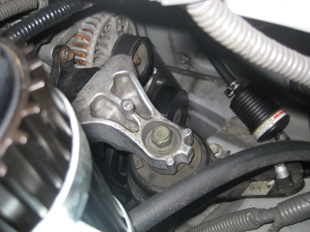
The Rotrex is located on the left front (intake) side of the engine near the firewall. The custom brackets from Web3.0 did not require any modification to the firewall and have a gusset to increase strength. The serpentine belt runs to all engine accessories and does not interfere with any of the mounting fasteners. Changing to NA configuration requires using a shorter belt but that is included with the car and is quick to change. You may have noticed that the Rotrex sits where the air conditioning compressor used to be. The AC was moved to the other side of the engine and the custom made Aeroquip high and low pressure hoses and fittings connect the compressor to the body mounted couplings. |
|
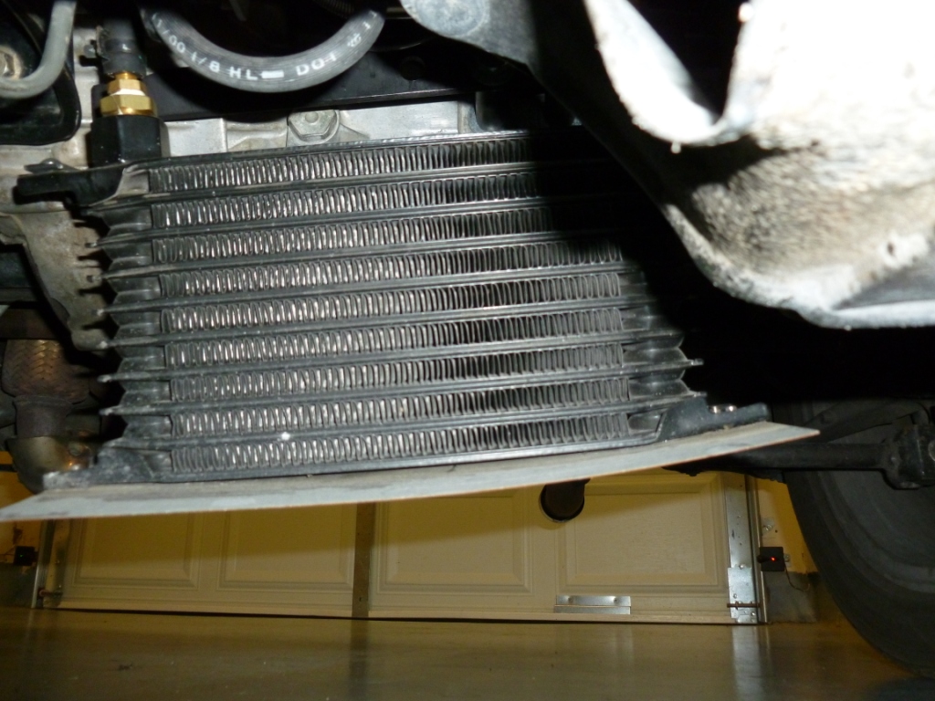
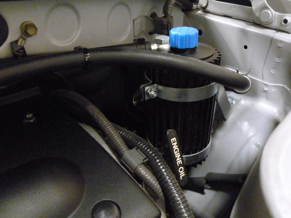
The Rotrex has its own self contained oiling system complete with a reservoir, filter, and heat exchanger shown below with a metal plate to scoop air through the fins. I have a sealed type K thermocouple in the line coming after the oil passes through the heat exchanger. The oil must not exceed 80C though I haven't seen it go above 50C in Texas weather. One of the fittings gave me grief and kept slightly leaking but I eventually tightened it enough to stop the leaking. |
|
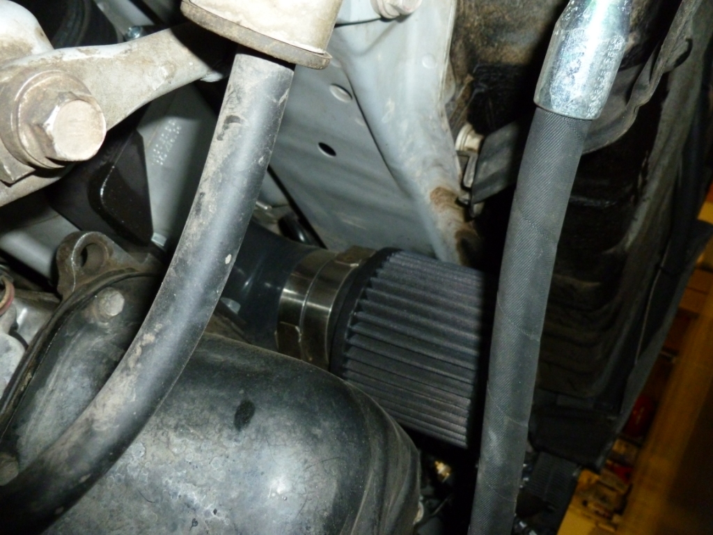
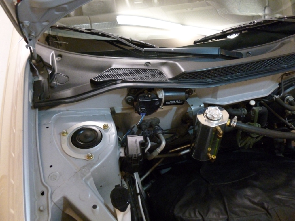
You can see the K&N air filter between the engine and firewall. There isn't much space down there but the filter is protected from most debris by the back of the firewall. If you are concerned about driving in the rain or going through puddles, you should move the location to higher ground by changing the silicon hoses. The filter itself is easy to remove for cleaning. |
|
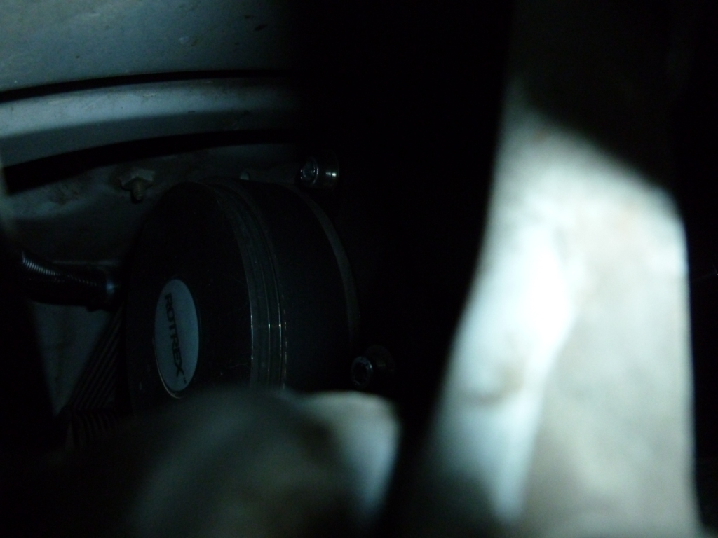
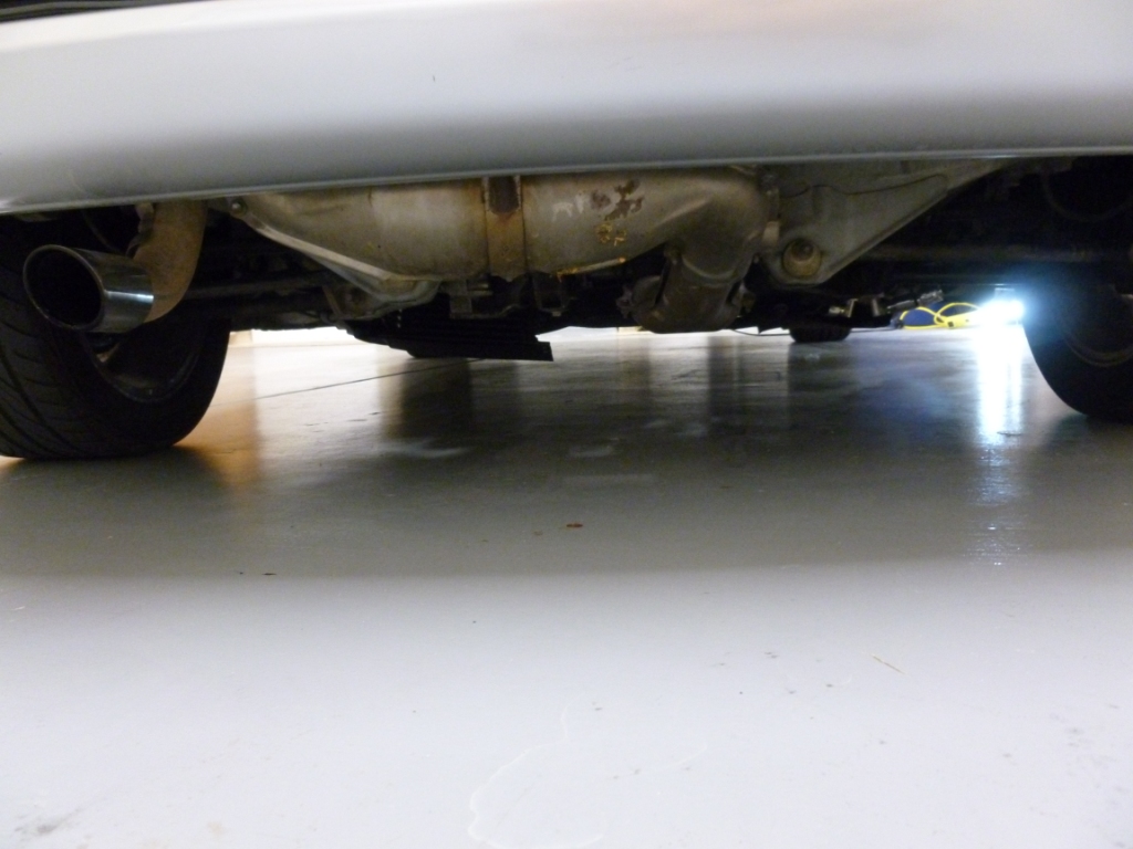
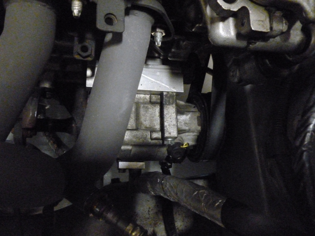
Another shot of the Rotrex from underneath. |
|
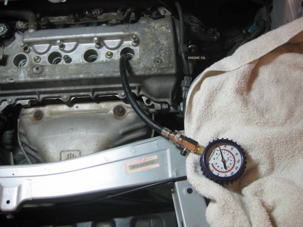
Before I started any of this, I checked the compression of all the cylinders to make sure they were within factory specs. It isn't good to boost a sick engine. I also checked the compression again after I had boosted it and drove it around for a while and it still looks good. You can also see the original stock header and heat shield, now removed. |
|
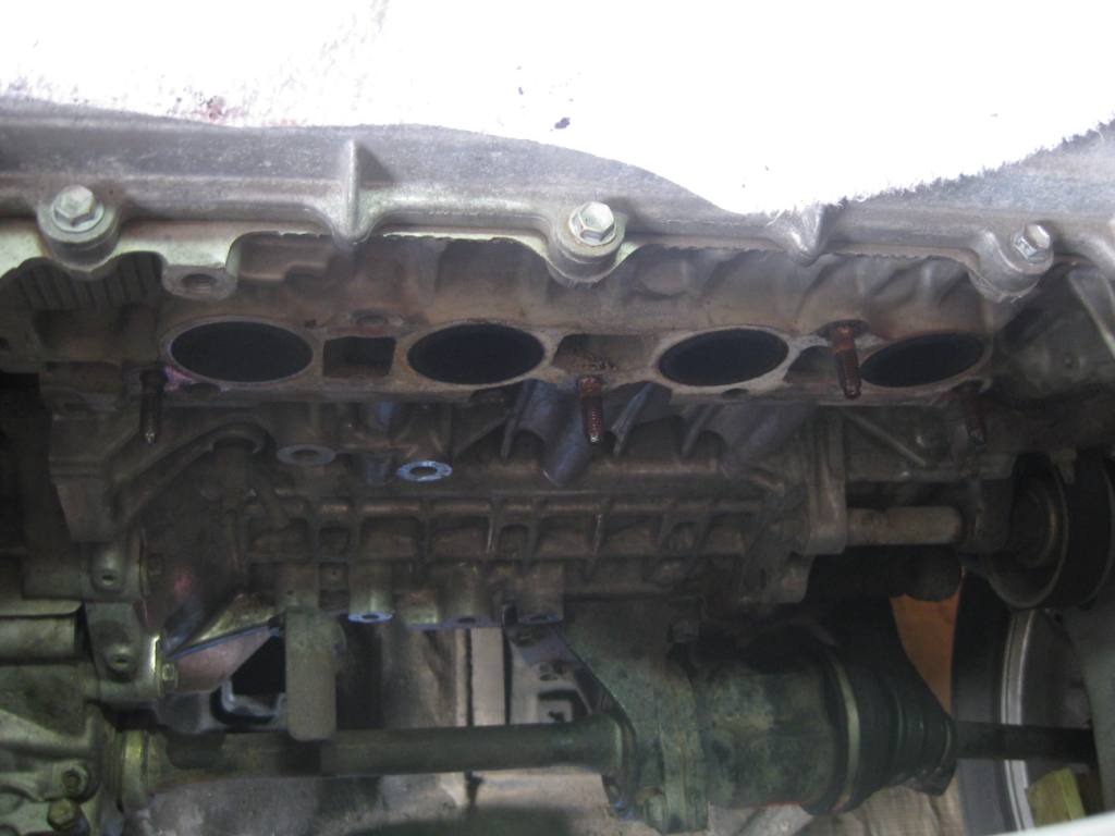
The exhaust ports were reasonably clean. I further cleaned them, installed new studs, a new OEM metal gasket, and a ceramic coated steel exhaust. The area just above the right driveshaft is where I eventually removed the idler pulley and installed the air con compressor. |
|
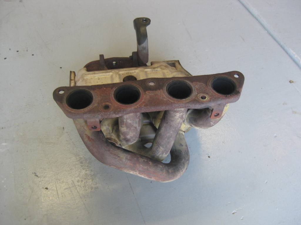
The old stock manifold with remnants of PB Blaster. |
|
The stock exhaust is in good shape and the three amigos have a few new studs and new gasket. This exhaust is restrictive and should be replaced for more power and better sound. |
|
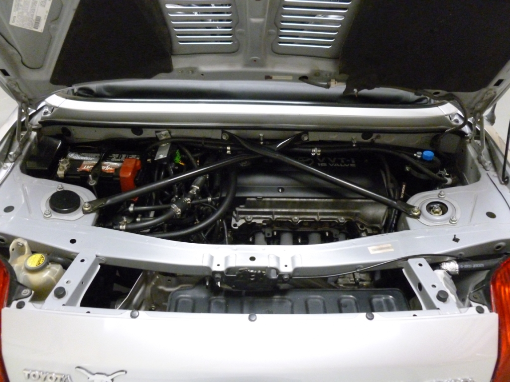
Here is the view of the engine bay. You can see the stock bracing, the catch cans, new header, Krankvents, MAP sensor, and Rotrex traction fluid reservoir which gravity feeds to the supercharger through the filter. You can also see one of the custom air con hoses that passes through the body panels but has thick PVC sleeves to protect from sharp sheet metal edges. You could alternatively put edging around the sheet metal but these work just fine. The drip pan for the louvers is remove to allow better engine bay breathing but you can put that back on if you decide to park it outside in the rain. |
|
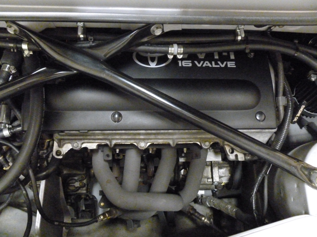
This is a better shot of the header, wideband O2 (left), OEM narrowband (right), and the new location for the air con compressor. I machined a custom plate and standoff blocks to allow rigid connection to the existing bosses protruding from the engine block. The hoses are somewhat wrapped to shield from the heat of the header and seem to do a great job because the air con blows really cold! |
|
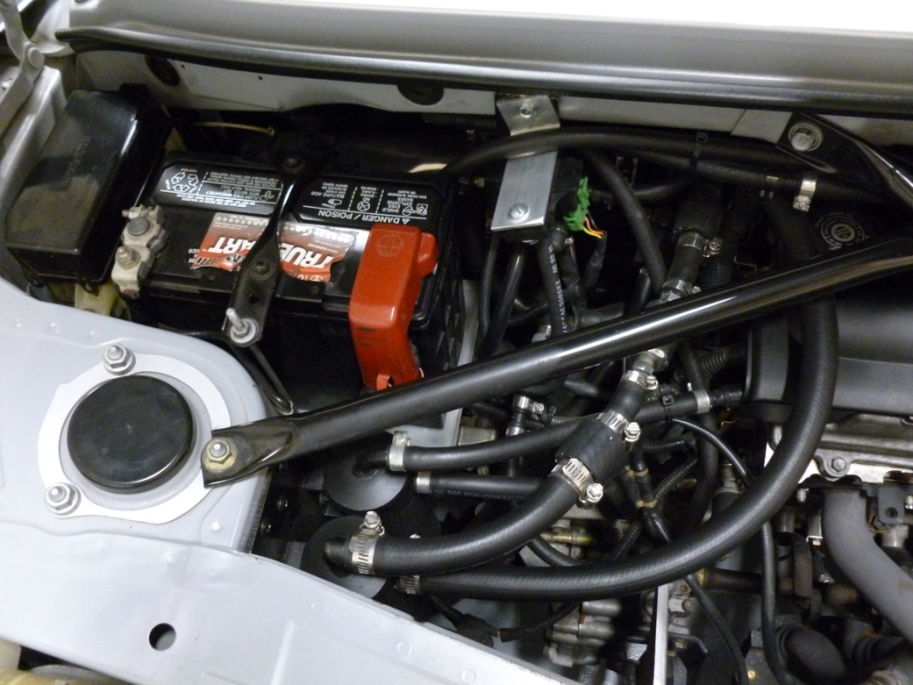
This is a better shot of the catch cans, the KrankVents, the MAP sensor (not required for operation, just to provide an electronic measurement for charge pressure), and the myriad of hoses. I custom machined a manifold block for all of the connections to the intake for the BOV and MAP. |
|
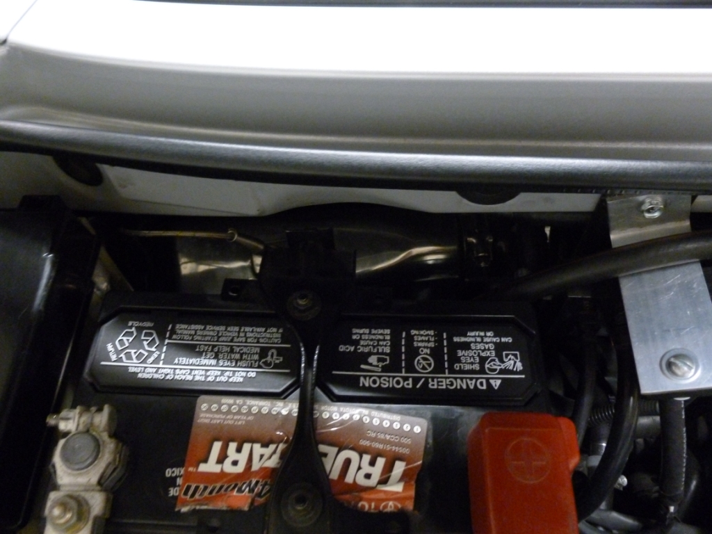
The water to air heat exchanger is mounted just behind the battery. There is a Type K exposed junction thermocouple sticking into the airflow measuring the cool side of the intake charge. The hot wire anemometer in the MAF makes a faster measurement but this can give you a measurement for generally comparing intake charge to ambient. |
|
The Rotrex traction fluid reservoir with its custom welded bracket that mounts to existing threaded holes on the body. |
|
A closer view of the custom mounted air con compressor. The custom mounting bracket was designed to fit in just the right position to avoid the belt rubbing on the engine casting and the compressor base from rubbing on the driveshaft. This was one of the most time consuming and frustrating parts of the setup but now it works perfectly. |
|
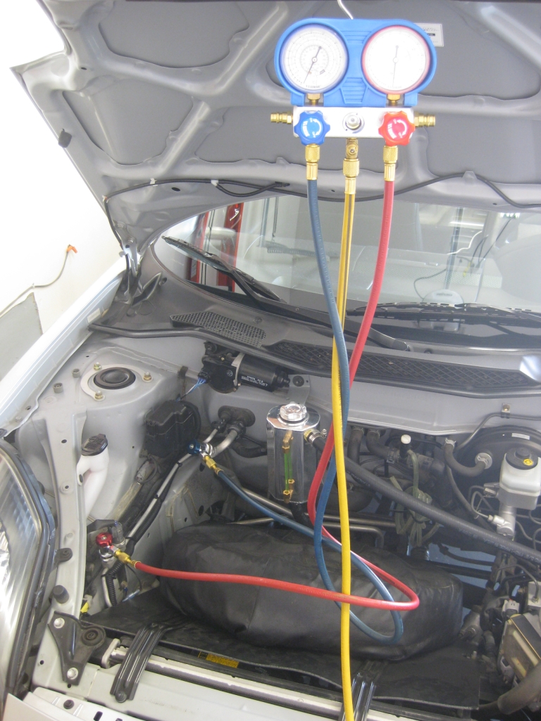
The low and high side connections for the air con system are in the frunk. The system was charged by Carter's Automotive in Austin after I couldn't find the source of a leak. They found that one of the aluminum custom fittings had a pinhole leak. The fitting was re-welded and the whole system is now leak free. |
|
The intercooler water reservoir is shown along with the re-mounting of the spare tire on a plastic panel that keeps road debris and hot air from the radiator from heating up the frunk. |
|
Another view of the reservoir and hose routing. |
|
The water pump runs on an add-a-fuse in the fuse panel just to the right of the strut tower. The wiring is well wrapped and hidden and is hard to discern. The original frunk plastics don't fit with the placement of the reservoir but could fit if a different shaped reservoir was used and re-routed. The frunk doesn't provide much space any way so I just removed it. |
|
The driver side of the frunk. |
|
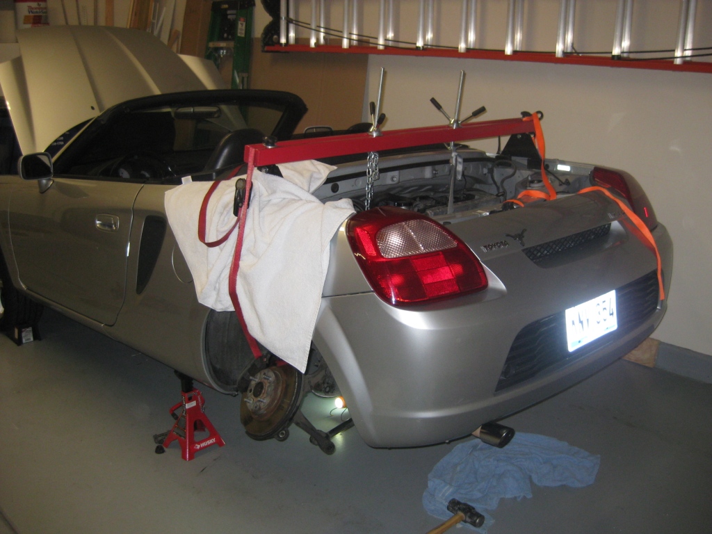
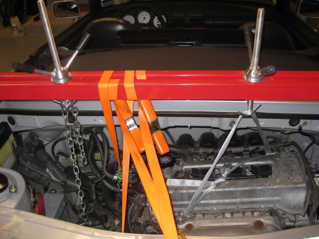
Replacing the clutch required tilting the engine to slide off the transmission. The bar shown makes supporting the engine and transmission easy while removing the mounts. |
|
Another shot of the bar and a system using straps, chains, and clamps to easily control the descent of the transmission. I will negotiate including the bar with the sale. |
|
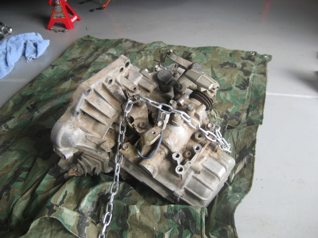
Removed transmission. |
|
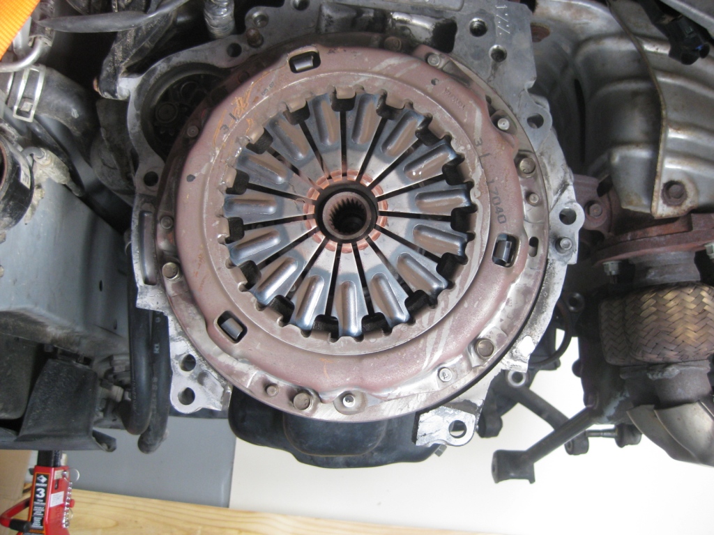
The stock clutch. |
|
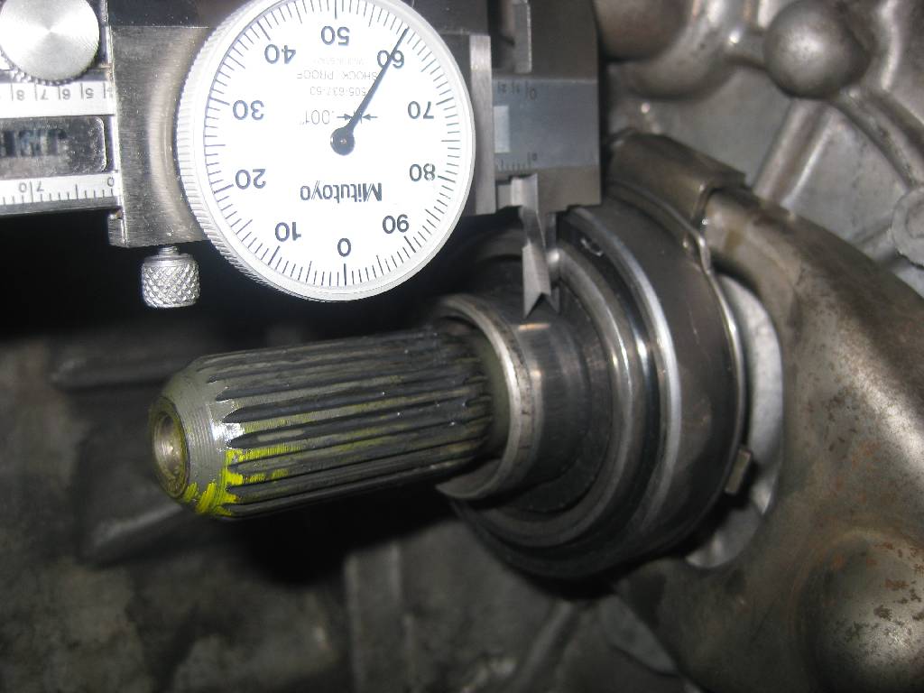
Checking the precision of the clutch fork and thowout bearing. I first tried a Fidanza clutch but it did not fit and gave me a lot of grief. I then went with the ACT HDSS which fit perfectly and holds plenty of torque. |
|
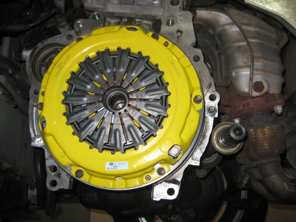
The flywheel was machined and installed with new OEM bolts with thread sealant pre-applied. This clutch is good for 300 hp and is very smooth driving around on the street. The pedal is slightly stiffer but is incredibly easy to drive and very forgiving. There is almost no chatter yet it holds on to all the power. |
 Top
Top